Tuesday, August 10, 2010

Fitting

After the enclosure was assembled I started to carefully drill holes using a Dremel (well, actually the cheapest version of a Dremel I could afford) into the underneath of the top plate corresponding to all the holes in the PCBs. The official Sparkfun plates are a two step process, with an assembly plate and a top plate so this is a little bit less pristine than that solution:

IMG_4480

IMG_4482 

Also I had a small problem with the DC power input of the Arduino so I had to drill away a little section on the inner side of the USB side plate to get the Arduino to fit flush on the outside… oops.

IMG_4481 

Then I screwed in the PCB boards with screws used to hold CD or HD drives in desktops – probably not the best to use (as they didn’t fit properly and in the 4 near holes I could usually only fit 2 in diagonally):

IMG_4485

IMG_4489

Then it was all done… time for the reveal…

IMG_4490

<deh nehnehneh neh neh>

IMG_4492

<twittwoo>

IMG_4493

IMG_4497

IMG_4499  <ding>

Then plugged it in to see if it worked………………………

IMG_4502

WOOHOOO!!!! … well not really, it didn’t work first off, during the fitting I had broken a few wires – but it was easy enough to fix so I won’t bore ye with the details.

IMG_4504

IMG_4512

Ok so it all works, next is to try and use it to make some music… hmm where to start….

Assembly

I’ve made all the 45 degree edge cuts to the laser-cut plates from Ponoko, now to put it all together. First we (my Dad and I) taped all the pieces in place:

IMG_4439

IMG_4441

Then used superglue on the inside seams and waited a day for it to dry completely:

IMG_4444

In order to make the box totally seamless, we decided to use magnets to hold the bottom plate in place. My Dad flies model planes a good bit so we cannibalised one of the motors (very similar to a CD ROM motor) and took out all the tiny but powerful magnets from the inside the main motor hub.

IMG_4445

IMG_4446

Then using a spare side piece as a prop for the bottom plate we worked out where to stick the magnets (using the key hole cut outs).

IMG_4447

IMG_4448

I think I used about 6 of these magnet pairs in the end, any fewer than that and the bottom would fall of when you picked it up – not good! :)

Enclosure II

Ok so the MDF rushed way didn’t work very well, but I still wanted a nice seamless box so after investigating a few different options I decided to go with Ponoko and get some laser-cut acrylic. I found a little tutorial at instructables, downloaded Google SketchUp and Inkscape and made a template for my monome. It’s a little bit wasteful to be fair, but I wanted to have a few spare parts to play about with in order to get the process right. If anyone wants my design you can get it here – but be warned it won’t all click together as is there’s a lot more work to be done!

I was very impressed with what I got from Ponoko, it looked so neat! And about a million times neater than my attempt with the MDF!! Laser-cut material is usually only ever cut at 90 degrees and I needed 45 degree cuts to make my seamless box – i.e. I didn’t want any dove joints or anything like that, I just wanted the join to be on the edge of the box.

Here’s a pic of what I got from Ponoko:

Ponoko laser cuts

With my Dad helping out (if I tried these parts on my own I wouldn’t have fingers to type this blog with) we set up a rig with a router and a table to cut the edges at 45 degrees. After a good bit of trial and error we finally got it so that it would cut away exactly at the edge give or take a few nanometres – it was very satisfying seeing the paper slightly curl up as we passed the pieces by the router. We ended up using a couple of bits of scrap metal to keep the rig as straight and level as possible – without these the wooden box had a natural dip in it from the weight of the router which would result in inconsistent edges. You could of course hire a proper router table but where’s the fun in that? Here’s a close up of the setup:

IMG_4430

Here’s a pass of the top plate:

IMG_4435 

And a corner of the bottom plate with 2 45 degree cuts (see how it’s going to come together yet?):

IMG_4431

We stuck the side pieces together to do them all in one pass (one has a laser cut hole for the usb port):

IMG_4429

Now all the plates have 45 degree cuts on all their edges, next step is to stick them all together…

Monday, November 3, 2008

Enclosure

That title sounds like some sort of crappy summer blockbuster action movie... starring Steven Segal as an ex-FBI agent turned Arduinome-maker??

Anyway, I needed to make some sort of enclosure for my Arduinome. The manky tea-towel you've seen my Arduinome resting on wasn't really going to cut it as a long term solution. I'm heading off travelling for a couple of months and I wanted to loan my Arduinome to a friend while I'm away so when I come back she can teach me how to use it :) So, I had to get it ready before I go - hence why the rest of my work is so rushed and looks like a drunk 5-yr old did it.... ok ok, drunk AND angry.

Initially I wanted to make an enclosure for it out of Lego & call the end result a Legome.  Lego have part of their site where you can order individual bricks - it's pretty expensive but I thought it would be perfect... until I saw the 22-business-day delivery time - so that was out the window.

Next on the list was MachineCollective's site - he makes kits for Arduinome enclosures - perfect!! Except he's having trouble with his suppliers so isn't currently taking orders :(

My next desperate attempt at getting an enclosure was to get a friend who does that sort of stuff for a living to make up a design file and get it prototyped. It was going to be really expensive but I thought at least it would look really cool. Unfortunately it turned out to be too big for their prototyping process.

So, my last ditch desperate attempt at getting an enclosure was to rely on myself and my skills to make one... bad.... BAD idea....

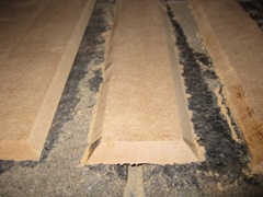
I got a 45° router bit, my dad's old router, some MDF, a workbench and some clamps and got started.  I wanted to make a seamless box (nice ambition for a first attempt eh?) so I cut out pieces for the sides and the top with 45° joins:

IMG_0169  IMG_0172

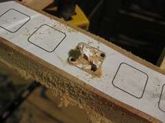
But I didn't have any 90° clamps so I couldn't join any of it together.  I decided to give the faceplate a try. I cut out one hole as a template.  The plan was to do a full row and just use a router to get nice and even holes using the template.  So I drilled out one, cleaned it up a bit and started the face:

 IMG_0175 IMG_0177IMG_0178IMG_0179

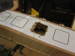
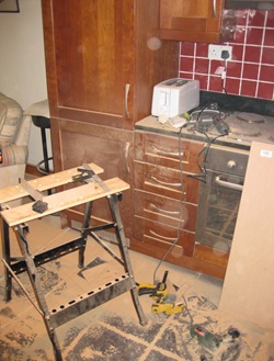
Somehow even using a template every hole came out different & I was really out of time because I had to clean this mess up:

IMG_0173

Oh well, Lilly will just have to use the patent-pending tea-towel enclosure until MachineCollective starts taking orders again.

Because my Legome dream is dead, I think it's much more appropriate to rename it to Ghettome.

Friday, October 31, 2008

Can't get mlr working...

Hey, I can't seem to get mlr working with my Arduinome & I don't know what I'm doing wrong.  I'm following all the readme's and instructions but it never seems to kick off and respond to me hitting the 2nd button down (I tried all the buttons just in case).

I followed the instructions from http://wiki.monome.org/view/InstallationXp to install (I've got quicktime installed too).

Here's what Arduinome Serial looks like (I had to type "mlr" manually into the Address Prefix Pattern - I couldn't find any /sys/prefix button on mlr like on the simpler newer apps):

mlr_arduinomeserial

And here's what mlr looks like (dac is up, volume is up, wavs are loaded, tap is blinking):

mlr_blank

It should - according to the docs - kick off when I press the leftmost button on the second row down on the monome - but no joy, nothing happens, nothing lights up and I can't hear anything.

Max does say "can't find plug-in, using default" in the main window whatever that means?  Also the docs say "max/msp must have the OSC objects installed" so I should find out what they are...

Anyone have the same problem?  I'm guessing it's got something to do with it being an Arduinome and not a monome - maybe the device id should be m40h-001 instead of a40h-001 for mlr to work???  Anyone any ideas? Please help!!

I've got a post on the forum here so hopefully I can get started soon :)

Update: thanks to guys on the forum (soundcyst & edison) I got mlr and 64beat working - I had to put "/box" into the prefix address on ArduinomeSerial.  Version 2.27 of mlr has a /sys/prefix button though, it can be found here. These apps are great fun to play with!

Wednesday, October 29, 2008

Daedelus gig was awesome!

The Daedelus gig in Limerick was brilliant - that guy is amazing!  I brought a few friends along who hadn't heard his stuff before and they really enjoyed it.  I wish I had a picture of it here to show ye...

I got a chance to chat with Daedelus (Alfred) for a bit too and told him all about my Arduinome.  Somehow (a few drinks perhaps) I ended up challenging him to a battle next time he comes to Ireland.  Also, somehow (also a few more drinks perhaps) I told him how badly he was going to lose and he would cry all the way back to LA using his sideburns to dry his eyes :D

Somehow (too many drinks) he burned me for being a David Hasselhoff fan - I'm not!! How did that happen?!? Ah it was all in good craic.

So I'd better get started training up for this battle...  I need to have the skills to pay the bills (there are a lot after this project)...  I think mlr is the main app for mixing and I've tried to get it running a few times but no joy.  Unlike the simpler test apps, mlr doesn't seem to have any /sys/prefix button so I tried setting the Address Prefix Path to "/mlr" manually, no joy.  I'll post to the forums and hopefully someone out there knows what the deal is.

ArduinomeSerialMlr

To pretty up the post, here's a picture or 2 of maxlife in action:

IMG_0144 IMG_0148

Mirrored

All the bad things I was saying about why you shouldn't follow my wiring show up here, basically my Arduinome ended up mirrored - nerdscroll showed this up best (that's supposed to be a J):

IMG_0140

To remedy I decided to flip the connector on the Arduinome shield as this would save me loads of rewiring on the SparkFun boards.  Bad, BAD idea.  Nope I hadn't been abusing the solder fumes lately... Here's how taking the pin headers out resulted:

IMG_0127

Here's how cleaning the holes out resulted:

IMG_0128

So I had to wire up a new shield, what a waste - I really should have just done the rewire on the SparkFun boards.  Now my set up is nothing as neat as it was before:

IMG_0135 IMG_0134

Under-side of Arduinome shield:IMG_0136 

What a mess... at least it's not mirrored any more:

IMG_0138

If there is anyone reading these out there I hope they realise (as I just have) that how-to's written by total amateurs (me) shouldn't be followed! :) you have been warned!