The initial wiring to breadboard I did with the solid core before I got my shield looked so messy & would break easily if it moved too much. Instead I decided to get some IDE ribbon just like the kind you might find in your housemate's desktop computer when he's not looking.
This title is called "how not to do it" because I'm in a rush and made some shortcuts which caused a big mess. In the next blog I'll write about a better way.
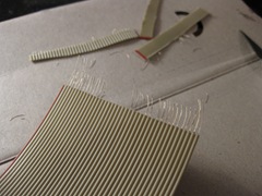
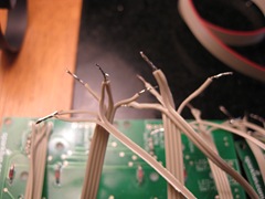
It took a couple of goes to get the stripping (taking the plastic off the end) right, the first few do-them-all-at-once attempts failed miserably:
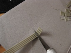
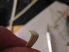
What I found worked well, was to make a small cut at the end of the cable for however many wires you need (usually 4), then pull this apart from the rest of the cable (cutting all the way I often missed and cut into the wire). Then I scored 1 cm from the end lightly, bent it back, then scored the other side - try not to cut into the wire itself. I found my teeth were the best wire-strippers once the initial cut was made - try not to actually eat the wire.
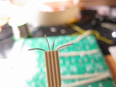
Next 'tin' the strands from each wire. Twist the strands of each individual wire so they are tight, then apply a small bit of solder with the iron along the twisted strands. This makes it much easier to solder to the PCB later and stop strands from touching the other wires.
Nomeist has a good diagram on how the wires should be soldered to the boards. I think if I were to do this project over again, I would look into getting a proper 8x8 board with all these wirings already done on the PCB - it's a really fiddly job. Meeker is in the process of making one (but for single colour non-RGB LEDs). I thought initially I'll end up with an RGB Arduinome, but retrospectively the single colour one would have been perfect for my needs.
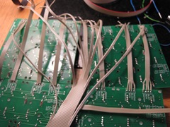
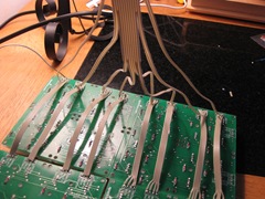
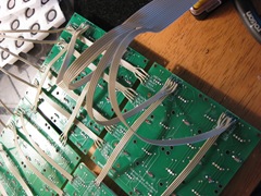
You can see how I wired up the boards from the next few diagrams. I thought I was doing ok and would save on wiring & connectors (my local Maplin only had 2 DIL 16 connectors & messed up my reorder). It turned out my monome ended up mirrored & it was a lot of work to get it back again.
You can learn from another one of my mistakes now - (if only I learned from my own mistakes):
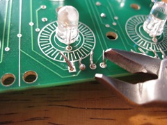
When you solder the wire to the PCB you should solder the other side (the side shown in the picture above). I don't know why I decided to solder the same side as the wire was on - perhaps my own stupidity, perhaps added stupidity from inhaling a load of burning wire plastic, at any rate it took a lot of stupidity.
Next is how I would imagine someone with some brains would do this... First though, I've to help my housemate with his computer - it won't boot for some strange reason..........
No comments:
Post a Comment